



Mobile Browsing
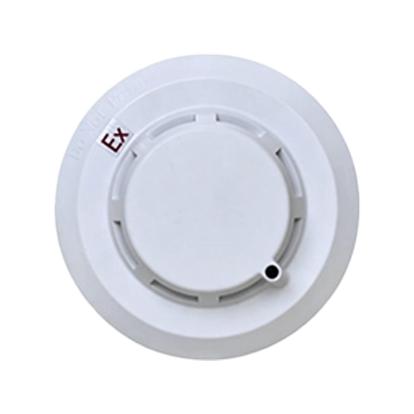
This product line includes point-type photoelectric smoke detectors, point-type heat detectors, and point-type combined smoke and heat detectors (hereinafter collectively referred to as "detectors"), featuring specially designed EMC resistance for stable and reliable performance. They are suitable for smoke and temperature detection and alarm applications in both civil and industrial settings such as rail transit, telecommunication base stations, shopping malls, warehouses, motor rooms, power distribution cabinets, energy storage cabinets, and high-temperature aging rooms.
All plastic materials used in the detectors are made of special fire-resistant materials, ensuring no deformation under prolonged exposure to high temperatures up to 120°C. The detectors offer high sensitivity, stable reliability, low power consumption, aesthetic durability, and user-friendly operation. Upon alarm activation, the red indicator light remains steadily illuminated, the buzzer emits a rapid audible alert (optional), and a set of relay passive normally open contacts is output (normally open or normally closed output configurable). The detectors are intended for use in conjunction with fire alarm and security control panels.
User Manual for Spot-Type Photoelectric Smoke/Heat Fire Detectors (High-Temperature Resistant Version)
1. Product Scope
Table 1: This user manual applies to all products listed in the table below.
Product Model | Product Name |
JTY-GM-RS311 | Spot-Type Photoelectric Smoke Fire Detector |
JTW-ZOM-RS311 | Spot-Type Heat Fire Detector |
JTF-GZOM-RS311 | Spot-Type Combined Smoke and Heat Fire Detector |
Note: Models with the "EP" designation indicate enhanced EMC interference resistance.
2. Product Overview
Spot-type photoelectric smoke fire detectors, spot-type heat fire detectors, and spot-type combined smoke and heat fire detectors (hereinafter collectively referred to as "detectors") feature specially designed EMC resistance and stable, reliable performance. They are suitable for smoke and temperature detection and alarming in civil and industrial environments such as rail transit, communication base stations, shopping malls, warehouses, motor rooms, power distribution cabinets, energy storage cabinets, and high-temperature aging chambers.
All plastic materials used in the detectors are special fire-retardant materials, ensuring no deformation under long-term high-temperature conditions of 120°C. The detectors are characterized by high sensitivity, stable and reliable performance, low power consumption, aesthetic and durable design, and ease of use. Upon alarm, the red indicator light remains steadily on, the buzzer sounds rapidly (optional), and a set of relay dry normally open contacts is output (normally open or normally closed output can be configured). These detectors must be used in conjunction with fire or security controllers.
3. Technical Specifications
Operating Voltage | 9 ~ 32VDC |
Operating Current | Standby current ≤0.5mA; Alarm current ≤50mA |
Indicator Light | Flashes during communication; Steady on during alarm |
Ambient Temperature | -40℃ ~ +120℃ (Note: 120℃ is the maximum temperature the detector housing and components can withstand. However, the maximum temperature for smoke alarm is 105℃. Detectors cannot alarm normally in environments where the temperature is consistently higher than this limit.) |
Relative Humidity | ≤95%RH (Non-condensing) |
Smoke Sensitivity | 0.2 ~ 0.3dB/m (Smoke detector) |
Alarm Temperature Class | A2R (Heat detector) |
Applicable Standards | GB4715-2005 / GB4716-2005 |
Dimensions | φ102 × 55mm |
Relay Contact Output Capacity | 1A @ 30VDC |
Alarm Sound Level | 80dB / 1m |
Housing Material & Color | ABS, White |
Wiring Terminal Material | Nickel-plated copper, Stainless steel |
Table 2: EMC Immunity Levels
Product | Standard Type | EP Enhanced Type |
Electrostatic Discharge | Air discharge: 8KV
| Air discharge: 15KV
|
Radiated RF Electromagnetic Field | 10V/m | 20V/m |
Electrical Fast Transient Burst | 1KV | 4KV |
Surge Immunity | 1KV | 4KV |
4. Working Principle
Smoke Detection Principle: The detector utilizes the infrared scattering principle to detect fires. In a smoke-free state, it receives only very weak infrared light. When smoke enters the optical smoke detection chamber, the scattering effect enhances the received light signal. When the smoke concentration reaches a certain level, an alarm signal is output.
Temperature Detection Principle: The detector uses an NTC (Negative Temperature Coefficient) thermistor as a sensor, utilizing its sensitivity to ambient temperature to acquire temperature information. The internal circuit converts this information into a voltage signal and transmits it to the microcontroller. The microcontroller analyzes and processes the signal using built-in intelligent algorithms and simultaneously determines whether the system is in a fire alarm or fault state.
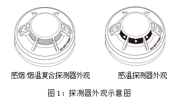
5. Structural Features
6. Installation and Wiring
6.1 Installation Standards
Protection area for smoke detectors: When the space height is below 6m, the protection area is 60 square meters.
Protection area for heat detectors: When the space height is below 8m, the maximum protection area for a single heat detector is 30 square meters.
Specific parameters shall comply with the "Code for Design of Automatic Fire Alarm System" (GB50116).
6.2 Unsuitable Installation Locations
Smoke fire detectors are not suitable for the following environments:
Locations with normal smoke retention;
Locations with significant dust, water mist, steam, oil mist, or corrosive gases;
Locations with ventilation speeds greater than 5m/s;
Locations with relative humidity greater than 95%.
Heat fire detectors are not suitable for the following environments:
Locations where smoldering fires may occur, or where failure to alarm promptly during a fire would cause significant losses;
Locations with significant temperature fluctuations (detectors with differential temperature characteristics should not be selected).
6.3 Installing the Detector Base
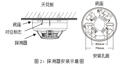
The installation hole spacing for the detector base is 42mm ~ 75mm. During installation, drill two 5mm diameter mounting holes 60mm apart on the ceiling. Use expansion plugs and screws to secure the detector base to the ceiling or the desired location, as shown in Figure 2.
6.4 Detector Wiring Instructions
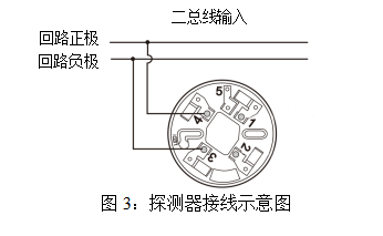
Table 3: Detector Wiring Terminal Function Table
端子序号 | 端子标识 | 端子功能 | 推荐导线 |
1 | 不用 | 建议采用线芯大于1.0平方毫米的普通双绞线,或屏蔽双绞线 | |
2 | 不用 | ||
3 | LOOP- | 总线回路负极 | |
4 | LOO+ | 总线回路正极 | |
5 | E | 连接线缆屏蔽层 | 可选项 |
6.5 Installing the Detector
After connecting the wires as shown in Figure 3, place the detector onto the base in the correct orientation. Press down and rotate clockwise to tighten.
Note: During installation, align the small vertical alignment mark on the detector with the first small vertical mark on the base. Then, rotate the detector clockwise until the detector's mark aligns with the second small vertical mark on the base (see Figure 2).
7. Product Functions
Normal Monitoring: The detector samples environmental smoke/temperature parameters approximately every 5 seconds and evaluates the status. The red indicator light flashes when receiving a polling signal from the controller.
Pre-alarm Status: When the detector detects that environmental smoke/temperature parameters have reached the alarm threshold, it accelerates the sampling and confirmation of these parameters. The red indicator light flashes rapidly (approximately once per second) as a prompt, while the detector re-confirms whether a genuine alarm has occurred.
Alarm Status: Once the detector confirms a genuine smoke alarm, the red indicator light remains steadily on.
8. Testing
Smoke Detectors: Use a dedicated smoke generator to blow smoke into the smoke detection chamber of the detector.
Heat Detectors: Use a hot air blower (ensure the temperature does not exceed 90°C) to directly blow hot air onto the temperature sensing element. Note: Do not use a lighter or open flame for direct testing to avoid melting the housing.
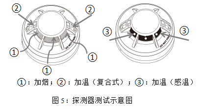
9. Maintenance
According to the national standard GB50166 "Code for Installation and Acceptance of Automatic Fire Alarm Systems": After smoke detectors are put into operation, they must be completely cleaned every 3 years. Corresponding threshold tests and other necessary functional tests must be conducted. Only detectors that pass the tests may continue to be used; those that fail are strictly prohibited from being reinstalled. Maintenance cycles for different application sites can be determined based on the specific usage environment.
10. Troubleshooting
A. No alarm output: Check if the jumper settings are correct.
B. False alarms: May be caused by excessive dust accumulation in the sensor maze. Please return the unit to a professional detector cleaning company for cleaning, or return it to the original manufacturer for processing.
11. Transportation and Storage
A. Transport and store the products in accordance with the provisions of GB/T15464-1995 "General Technical Conditions for Packaging of Instruments and Meters".
B. The original factory packaging and seals must remain intact during transportation and storage, and the product must be protected from severe impact.
C. The stacking height of boxed products must not exceed 6 layers. After unpacking, the stacking height of individual units must not exceed 5 layers.
12. Company Information
Shenzhen Tengyun Ruishi Technology Co., Ltd.
Address: 6th Floor, Building G, Guancheng Low-Carbon Industrial Park, Shangcun Community, Gongming Street, Guangming District, Shenzhen Phone: 0755-29955195
13. Product Certification Information

Product Model | JTY-GM-RS311 | JTW-ZOM-RS311 | JTF-GZOM-RS311 |
Operating Voltage | 9 ~ 32VDC | ||
Operating Current | Standby Current ≤0.5mA / Alarm Current ≤50mA | ||
Indicator LED | Flashes during communication, steady on during alarm | ||
Ambient Temperature | -40℃ ~ +120℃ | ||
Relative Humidity | ≤95%RH (Non-condensing) | ||
Smoke Sensitivity | 0.2 ~ 0.3dB/m (Smoke Detector) | ||
Alarm Temperature Class | A2R (Heat Detector) | ||
Compliance Standards | GB4715-2005 / GB4716-2005 | ||
Dimensions | φ102×55mm | ||
Relay Contact Output Capacity | 1A@30VDC | ||
Alarm Sounder | 80dB / 1m | ||
Housing Material & Color | ABS, White | ||
Wiring Terminal Material | Nickel-plated Copper, Stainless Steel | ||
Previous:Flame Detector
Next :Fire extinguisher bank